

 English
 عربى
عربى
News
Home / News / Industry News / What Is a Rotational Float Mold? Design, Materials, Applications, and Manufacturer Selection Guide
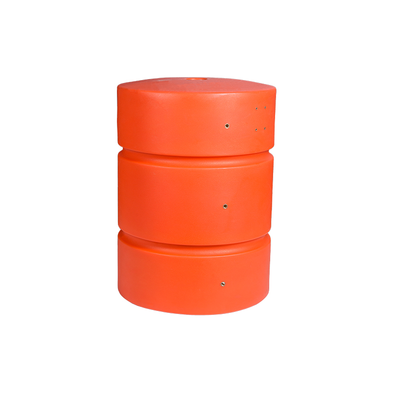
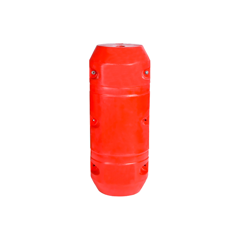
A rotational float mold is a precision-engineered hollow tooling used in the rotational molding (rotomolding) process to produce seamless, buoyant plastic float structures — including marine buoys, dock floats, aquaculture cages, navigation markers, and industrial pontoons. The mold defines the shape, wall thickness distribution, and surface finish of every float it produces. Because rotomolding is the only mainstream plastic manufacturing process capable of producing large, closed hollow structures in a single seamless piece, the quality of the rotational float mold directly determines the structural integrity, buoyancy consistency, and service life of every float it produces. This guide covers how these molds are designed, what they are made from, where they are used, and how to select the right manufacturer.
The rotational molding process begins by loading a precisely weighed charge of plastic powder — almost always linear low-density polyethylene (LLDPE) or cross-linked polyethylene (XLPE) — into the rotational float mold. The mold is clamped shut and mounted on the arm of a rotomolding machine, then moved into an oven heated to 260–370°C (500–700°F). While inside the oven, the mold rotates simultaneously on two perpendicular axes at low speed — typically 4–20 RPM on the primary axis and 1–8 RPM on the secondary axis, with the ratio between the two axes carefully set to ensure even resin distribution across all interior surfaces.
As the mold heats, the polyethylene powder melts and coats the interior cavity walls. The rotation ensures the molten resin reaches every surface, corner, and geometric feature of the mold interior before solidifying. After the oven cycle — typically 15–40 minutes depending on wall thickness and part geometry — the mold moves to a cooling station where forced air, water mist, or ambient cooling solidifies the plastic while rotation continues. Once cooled to demolding temperature, the mold is opened and the finished float is extracted as a single seamless hollow part.
The rotational float mold itself is passive in this process — it provides only shape and thermal conduction. No injection pressure, no blow pressure, and no hydraulic force acts on the mold during production. This fundamental difference from injection or blow molding means rotational float molds operate under far lower mechanical stress, allowing aluminum tooling to produce hundreds of thousands of cycles without fatigue failure.
The parting line is where the two (or more) mold halves meet and separate for part extraction. For float molds, parting line placement is a primary design decision because it determines:
Rotomolding naturally produces uniform wall thickness across simple geometries. However, in float molds with sharp internal corners, deep ribs, or complex surface features, resin bridging and pooling can create thin spots at corners and thick accumulations at flat surfaces. Experienced float mold designers apply the following rules:
As the mold heats in the oven, air inside the closed mold cavity expands. Without venting, pressure buildup forces molten resin away from mold surfaces, creating bubbles, voids, and surface pitting on the finished float. Rotational float molds require vent tubes — typically 6–12mm diameter PTFE-lined steel tubes — inserted through the mold wall at the highest point of the cavity during heating. Vents are sized to relieve thermal expansion pressure without allowing resin to escape. Vent plugs are installed before cooling to prevent outside air from introducing moisture that causes internal porosity.
Rotational float molds can incorporate metal inserts molded directly into the plastic wall during the rotomolding cycle — stainless steel lifting eyes, mooring ring anchors, threaded pipe bosses, and drainage bungs. The insert is positioned inside the mold before loading the resin charge; as the plastic melts and coats the mold interior, it encapsulates the insert flange. Properly designed inserts for rotomolding have perforated or undercut flanges that the plastic flows through and locks around — pull-out strengths of 5,000–15,000 N are achievable for stainless steel inserts in 8mm LLDPE walls, sufficient for mooring loads on all but the largest commercial buoys.
The choice of mold material is one of the most consequential decisions in rotational float mold procurement, affecting tool cost, lead time, part quality, thermal efficiency, and service life.
The industry standard for production rotational float molds. Cast aluminum offers:
Welded mild steel or stainless steel molds are used for:
Produced by electrodepositing nickel onto a mandrel of the float geometry, then backing the shell with an aluminum or epoxy support structure. Electroformed molds reproduce surface texture and detail at sub-0.01mm resolution — used for premium consumer floats, branded navigation buoys with embossed logos, and floats requiring Class A surface finish that cannot be achieved by machined aluminum. Cost is significantly higher than cast aluminum — $25,000–$100,000+ for complex geometries — and lead times exceed 20 weeks.
| Mold Material | Thermal Conductivity | Typical Tool Cost | Lead Time | Service Life (Cycles) | Best For |
|---|---|---|---|---|---|
| Cast Aluminum | ~160 W/m·K | $15,000–$60,000 | 8–16 weeks | 3,000–10,000+ | Production volume, complex geometry |
| Fabricated Steel | ~50 W/m·K | $5,000–$25,000 | 4–8 weeks | 1,000–5,000 | Large formats, prototypes, low volume |
| Electroformed Nickel | ~90 W/m·K | $25,000–$100,000+ | 16–24 weeks | 5,000–15,000 | Premium surface finish, fine detail |
The plastic resin processed through the rotational float mold determines the float's buoyancy, impact resistance, UV durability, and chemical resistance. The dominant resins for float production are:
The workhorse resin for rotomolded floats. LLDPE offers excellent impact resistance (notched Izod 800–1,000 J/m), good UV stability with proper additive packages, and a density of 0.918–0.940 g/cm³ — low enough to contribute positive buoyancy at practical wall thicknesses. LLDPE processes cleanly in rotomolding at oven temperatures of 300–340°C and is available in a wide range of melt index grades suited to different part wall thickness targets. The vast majority of commercial marine buoys, dock floats, and aquaculture floats worldwide are produced in LLDPE.
XLPE undergoes a chemical cross-linking reaction during the oven cycle, forming a three-dimensional polymer network that significantly improves stress crack resistance, elevated temperature performance, and long-term creep resistance compared to LLDPE. XLPE floats are specified for applications involving continuous chemical exposure, elevated water temperatures (geothermal aquaculture, industrial effluent containment), or sustained heavy load. The cross-linking reaction is irreversible — XLPE floats cannot be recycled by re-melting, which is a lifecycle sustainability consideration for large-scale float deployments.
HDPE grades formulated for rotomolding offer higher stiffness than LLDPE — useful for large flat-panel dock float decks where deflection under load must be minimized — but lower impact resistance and more challenging processing behavior. HDPE rotomolding grades require tighter oven temperature control to avoid degradation. Used selectively for dock float deck panels and large pontoon structures where surface rigidity outweighs impact toughness in the design priority list.
Marine and outdoor floats require resin compounded with UV absorbers and hindered amine light stabilizers (HALS) at 0.3–0.8% loading to prevent surface chalking, embrittlement, and color fading under continuous solar exposure. Navigation buoys and hazard markers use specific colorfast pigment systems — IALA (International Association of Marine Aids to Navigation) standard colors (red, green, yellow, black, white) must retain color accuracy after 10 years of outdoor exposure to meet certification requirements in most maritime jurisdictions.
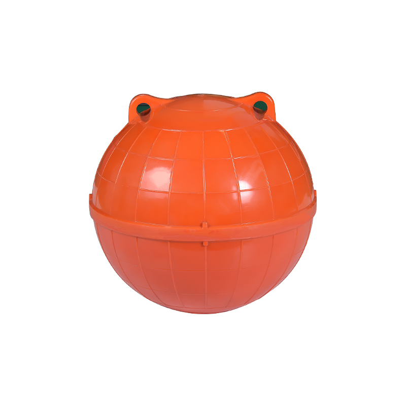
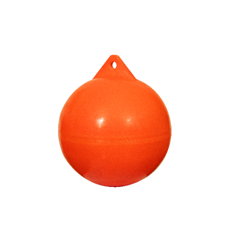
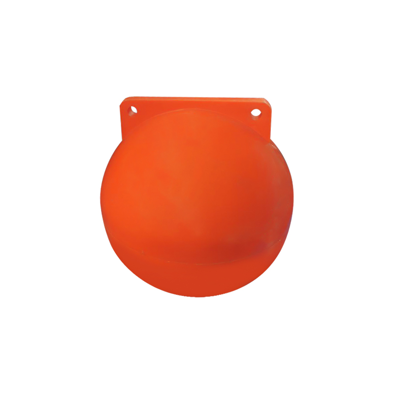
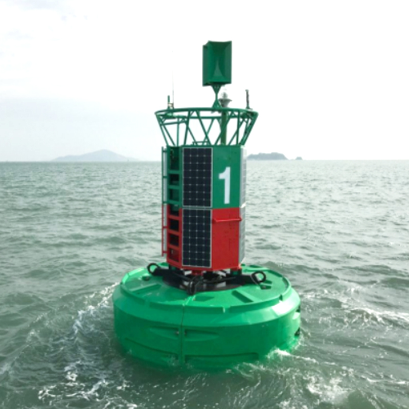
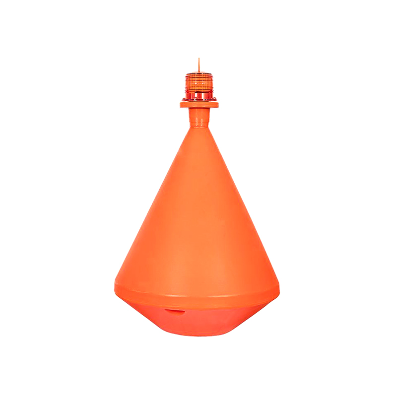
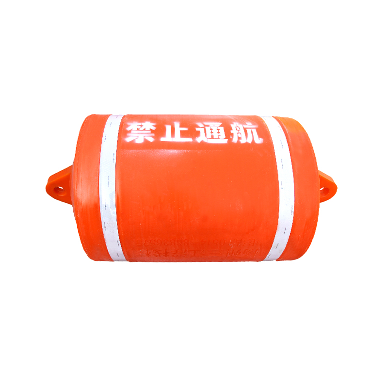
Channel markers, fairway buoys, hazard markers, and mooring buoys produced in rotational float molds serve in harbors, rivers, offshore shipping lanes, and coastal approaches worldwide. Rotomolded LLDPE navigation buoys are specified by coast guards and port authorities in over 80 countries as the standard replacement for legacy steel buoys — offering corrosion immunity, lower maintenance cost, and comparable structural performance at 40–60% lower unit weight. Standard sizes range from 300mm diameter (small channel markers) to 2,400mm diameter (offshore cardinal marks and large fairway buoys).
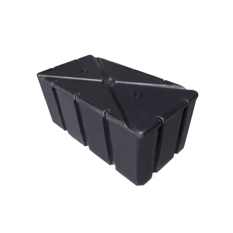
Modular floating dock systems use rotomolded float pontoons as the buoyancy elements beneath dock decking. Each float module — typically 600mm × 600mm to 1,500mm × 3,000mm in plan — is produced from a single rotational float mold with integrated connector hardware molded in. A marina serving 100 berths may incorporate 500–2,000 individual float modules, all produced from a small family of 3–5 mold sizes. The seamless rotomolded construction is critical in this application — fabricated float modules with welded seams fail within 3–7 years in tidal marina environments; rotomolded units routinely exceed 20–25 years of service life in the same conditions.
Offshore and nearshore fish farming operations use rotomolded floats for:
Beyond marine applications, rotational float molds produce buoyancy elements for:
| Application | Typical Float Size | Wall Thickness | Preferred Resin | Key Mold Feature |
|---|---|---|---|---|
| Navigation buoy | 300–2,400mm dia. | 8–20mm | LLDPE / XLPE | Molded-in mooring ring boss |
| Dock float module | 600×600mm – 1500×3000mm | 6–10mm | LLDPE / HDPE | Integrated connector pockets |
| Aquaculture cage collar | 250–500mm dia. tube | 6–10mm | LLDPE | End cap and connector interface |
| Floating solar pontoon | 400×800mm – 600×1200mm | 5–8mm | HDPE / LLDPE | Panel mounting rail integration |
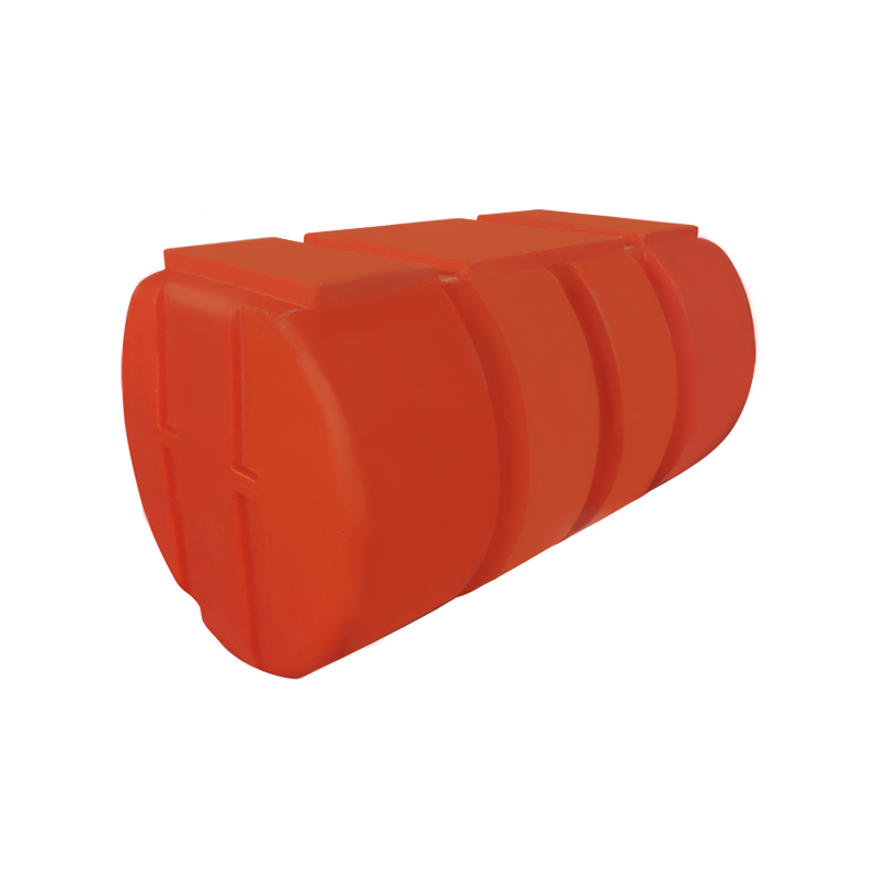
| Dredge pipeline float | 500–900mm dia. × 1–2m | 10–15mm | XLPE | Central pipe passage bore |
Rotational molding toolmakers who specialize in general industrial parts — crates, tanks, playground equipment — do not automatically possess the expertise required for marine float molds. Float molds require specific knowledge of buoyancy geometry, waterline parting line placement, molded-in hardware integration, and marine-grade surface finish standards. Request a portfolio of completed float mold projects with verifiable end-customer references in the marine, aquaculture, or navigation sectors before shortlisting any manufacturer.
The best rotational float mold manufacturers provide full DFM (Design for Manufacturability) analysis before committing to tooling. This includes:
Manufacturers who require the customer to supply complete, production-ready 3D mold designs without offering DFM input are operating as pure fabrication shops — acceptable for experienced float producers but a significant risk for first-time buyers.
Cast aluminum rotational float molds must be CNC-machined after casting to achieve functional dimensional accuracy. Confirm that the manufacturer operates CNC machining centers with working envelopes sufficient for your mold size — a manufacturer whose largest CNC table is 1m × 1m cannot accurately machine a 2m × 3m dock float mold half. Request tolerance specifications for the finished mold cavity — ±0.5mm on critical float dimensions (connector pocket locations, boss centerlines, parting line flatness) is the minimum standard for production float tooling.
A professional rotational float mold manufacturer will conduct first article inspection (FAI) on the initial production parts from every new mold, providing a dimensional report against the engineering drawing. For marine floats, FAI should include:
Clarify tooling ownership before signing any purchase agreement. In most commercial arrangements, the customer who pays for the rotational float mold owns the tool — but this must be explicitly stated in the contract. Some manufacturers attempt to retain tooling as leverage against customers who switch production to a different rotomolder. Confirm also whether the manufacturer retains the right to produce identical or similar floats for competitors using your mold geometry — a critical IP protection issue for proprietary float designs.
Reputable rotational float mold manufacturers provide a minimum 12-month warranty against casting defects, machining errors, and premature wear under normal rotomolding conditions. Warranty should explicitly cover repair or replacement of mold sections that develop cracks, surface pitting, or dimensional shift within the warranty period. Ask about the manufacturer's policy on mold refurbishment — re-machining of worn parting line surfaces, re-coating of mold interiors, and repair of damaged vents and inserts — as these services extend productive mold life significantly beyond the initial warranty period.
The purchase price of a rotational float mold is only one component of its total cost of ownership. A complete evaluation must include:

 wuyuqiao village, Henghe Town, Cixi City, Zhejiang Province
 +86-15257871220
 [email protected]
